Archive for the ‘Experiments’ Category
Stupid Pet Trick: Weather Control
This trick is an example of serial communication. Data is sent from a control wheel to an Ardiuno, and then finally to a Processing sketch on my computer.
View video of the silly trick in action:
StupidPetTrick_RainMaker from Corrie Van Sice on Vimeo.
and here’s a screen capture for more detail:
RainMakerProcessingCapture from Corrie Van Sice on Vimeo.

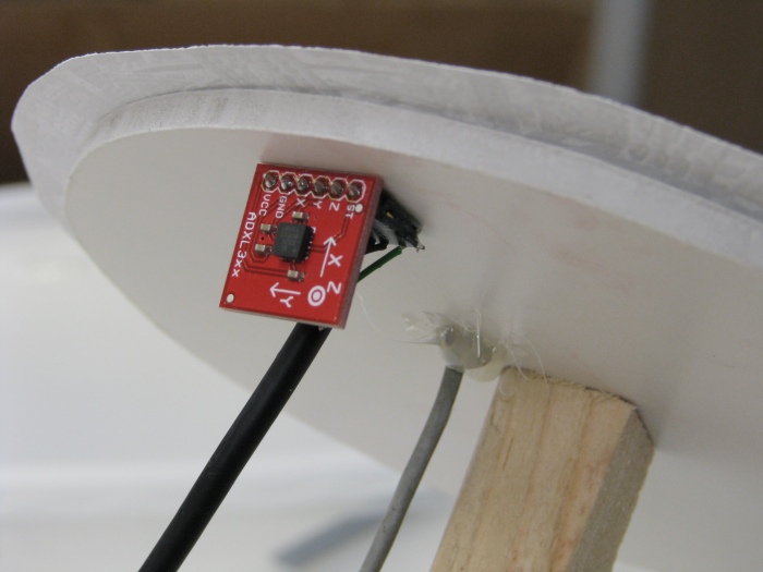
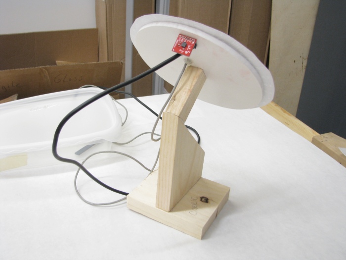
A 3-axis accelerometer and a photo-sensor are attached to the back of the control wheel. The photo-sensor is embedded into the piece of foamcore so that only a thin piece of paper diffuses light getting to the sensor. This way the sensor is hidden, yet it is still sending a good range of values to the Arduino.

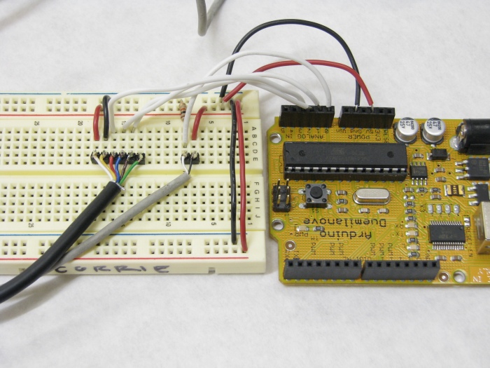
Here you can see the circuit sending analog values into the Arduino controller. The photo-sensor only uses two leads for power and ground, and a 10K pull down resistor. It is connected to analog-in pin 0. The accelerometer uses 6 pins:
1) X-axis goes to analog-in pin 3
2) Y-axis goes to analog-in pin 2
3) Z-axis goes to analog-in pin 1
4) 5V
5) Ground
6) ST (i don’t use this one)

As I mentioned before, I am using both Arduino and Processing, so I have two sketches. Here is the Arduino program which I uploaded to the board. It is collecting 4 pieces of information: the x-axis tilt, the y-axis tilt, the z-axis tilt, and the value from the photo-sensor:
int xpin = 3; // x-axis of the accelerometer
int ypin = 2; // y-axis
int zpin = 1; // z-axis (only on 3-axis models)
int psensPin = 0; //photo-resistor
int x = 0;
int y = 0;
int z = 0;
int light = 0;
void setup()
{
// initialize the serial communications:
Serial.begin(9600);
}
void loop()
{
x = analogRead(xpin);
y = analogRead(ypin);
z = analogRead(zpin);
light = analogRead(psensPin);
// print the sensor values:
Serial.print(x);
// print a tab between values:
Serial.print(“,”);
Serial.print(y);
// print a tab between values:
Serial.print(“,”);
Serial.print(z);
Serial.print(“,”);
Serial.print(light);
Serial.println();
}
This next sketch is the Processing program. Notice that it only uses the y-axis value and the photo-sensor value as variables in the sketch. The photo-sensor value controls both the darkness of the sky (via a variable for the blue in the background) and the quantity of rain drops on screen. The y-axis value controls wind direction and wind intensity. The values to be mapped from the photo-sensor must be adjusted according to light conditions in the environment. Also, the multiplier controlling the quantity of rain drops. In the relatively dark PhysComp workshop, I used a multiplier of 2.8, but in a brighter area I only needed to use a multiplier of 2:
Drop[] drops = new Drop[500];
import processing.serial.*; // import the Processing serial library
Serial myPort; // The serial port
float Bval;
float xspeed;
int amt;
void setup() {
println(Serial.list());
myPort = new Serial(this, Serial.list()[0], 9600);
// read bytes into a buffer until you get a linefeed (ASCII 10):
myPort.bufferUntil(‘\n’);
size(1024,768);
smooth();
noStroke();
for (int i = 0; i < drops.length; i++) {
drops[i] = new Drop(random(5),random(width),0,random(5, 10));
}
}
void draw() {
fill(164, 191, Bval, 60);
rect(0, 0, width, height);
for (int i = 0; i < 500-amt*2.8; i++) {
drops[i].move(xspeed);
drops[i].boundaryCheck();
drops[i].display();
}
}
void serialEvent(Serial myPort) {
// read the serial buffer:
String myString = myPort.readStringUntil('\n');
// if you got any bytes other than the linefeed:
if (myString != null) {
myString = trim(myString);
// split the string at the commas
// and convert the sections into integers:
int sensors[] = int(split(myString, ','));
// print out the values you got:
for (int sensorNum = 0; sensorNum 1) {
Bval = map(sensors[3], 20,200,180,255);
xspeed = map(sensors[1], 420, 600, -3, 3);
amt = sensors[3];
}
}
}
class Drop {
float x;
float y;
float yspeed;
float d;
Drop(float tempD, float tempX, float tempY, float tempySpeed) {
d = tempD;
x = tempX;
y = tempY;
yspeed = tempySpeed;
}
void move(float xspeed) {
y = y + yspeed;
x = x + xspeed;
}
void display() {
fill(255);
ellipse(x,y,d,d);
}
void boundaryCheck() {
if (y > height+20) {
y = -20;
}
if (x > width+20) {
x = -20;
}
if (x < -20) {
x = width + 20;
}
}
}
Week One, Switch Experiment
Hoping to make a “flex sensor” from scratch, I lined up 5 copper contacts on a bendable base of paperboard like shingles layered over a roof. Bending the strip of switches lifts the shingles, opening each switch progressively, at least in theory. Each switch corresponds with an LED wired to the breadboard and they illuminate as the bend decreases. I wired my multi-switch wrong initially, so in the end, the red wires represent negative and the black represent positive. The Arduino code was simplified using 2 arrays to contain the LED output pins and the switch input pins, like so:
int ledArray[] = {2, 3, 4, 5, 6}; //an array for the LEDs
int switchArray[] = {9, 10, 11, 12, 13}; //an array for the switches
int selector = 0; //value of switches
void setup(){
for (int i=0;i<5;i++){
pinMode(ledArray[i], OUTPUT); //set all the LED pins to outputs
pinMode(switchArray[i], INPUT); //set all the switch pins to inputs
}
}
void loop(){
for (int i=0; i<5; i++){ //for items 0-4
selector = digitalRead(switchArray[i]); //read the corresponding switch pins
if (selector == HIGH){ //if they are connected
digitalWrite(ledArray[i], HIGH); //turn the corresponding LED on
}
if (selector == LOW){ //if not, turn the LED off
digitalWrite(ledArray[i], LOW);
}
}
ITP, P-Comp, Week One, 5-part Bendy Switch from Corrie Van Sice on Vimeo.